- Thermal energy
- Chemical energy
- Electrical energy
- Radiant energy (energy of electromagnetic waves)
- Nuclear energy
- Magnetic energy
- Elastic energy
- Sound energy
- Mechanical energy
Tuesday, December 7, 2010
Different Forms of Energy
Energy is an essential part of our daily lives. Yet, it has puzzled and fascinated scientists for many centuries. Energy is a very abstract concept that is often defined as "the ability a physical system has to produce changes on another physical system". Therefore, energy can take on many different forms. Some of these forms include:
Wednesday, December 1, 2010
How To Maximize a Cannon's Horizontal Range
In order to maximize a cannon's horizontal range, the angle of the barrel must be set to 45 degrees above the horizontal (assuming all other things like the size of the projectile and the power of the propellant are equal, level ground, and no air resistance). This optimal angle can be proven using the formula for the range of a projectile:
R = V²sin(2θ)/g
Using this formula, we can determine the value of θ that will maximize the value of sin(2θ), which will maximize the range of the projectile since v and g do not change. The maximum value of sin(2θ) is 1, which occurs at sin(90). Therefore the value of θ must be 45 degrees above the horizontal.
Tuesday, November 30, 2010
The Best Cannons Ever
A cannon is a piece of artillery that uses an explosive-based propellant to launch a projectile at the enemy. It is mostly used to destroy the enemy's defensive structures and vehicles. The simplest design of a cannon consists of a barrel with one end sealed shut. A quantity of propellant and a projectile are put into the barrel so that they collect at the shut end of the barrel. The propellant is then ignited and the projectile is propelled out of the barrel. Throughout history there have been many examples of totally gnarly cannons. Here are some examples:
1. The Tsar Cannon
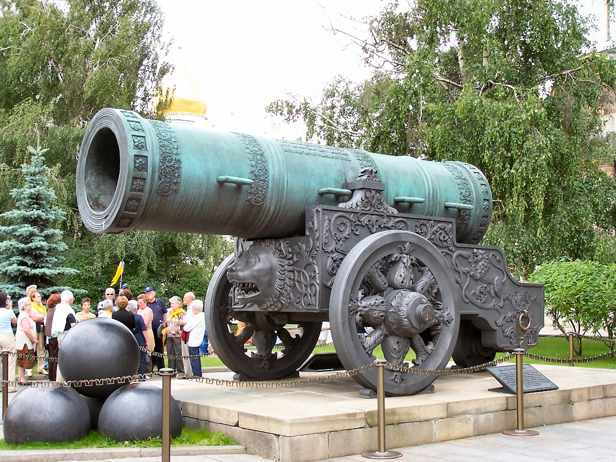
The aptly named Tsar Cannon is the largest old-fashioned cannon ever made. It was built by the Russians in 1586, but it was never used in combat.
2. The Paris Gun

The Paris Gun was a long-range siege cannon that the Germans used to bomb Paris during WWI. This gun had such a great range that the French thought they were being bombed by a new type of high-altitude zeppelin rather than a cannon.
3. V-3 Cannon

The Nazis had planned to use this super-cannon to bomb London from a secret bunker across the English Channel. However, it was damaged beyond repair before it was completed.
4. 2B1 Oka

This self-propelled cannon made by the Soviets was so powerful that its recoil caused damage to the vehicle itself.
5. Mallet's Mortar

This cannon was built by the British in 1857, but it was never used in combat. Just look at the size of those projectiles!!
1. The Tsar Cannon
The aptly named Tsar Cannon is the largest old-fashioned cannon ever made. It was built by the Russians in 1586, but it was never used in combat.
2. The Paris Gun
The Paris Gun was a long-range siege cannon that the Germans used to bomb Paris during WWI. This gun had such a great range that the French thought they were being bombed by a new type of high-altitude zeppelin rather than a cannon.
3. V-3 Cannon
The Nazis had planned to use this super-cannon to bomb London from a secret bunker across the English Channel. However, it was damaged beyond repair before it was completed.
4. 2B1 Oka
This self-propelled cannon made by the Soviets was so powerful that its recoil caused damage to the vehicle itself.
5. Mallet's Mortar
This cannon was built by the British in 1857, but it was never used in combat. Just look at the size of those projectiles!!
Friday, November 26, 2010
Solving Newton's Second Law Problems
Our physics class has been spending the past few days perfecting the art of solving problems that apply Newton's second law of motion. These problems use the formula: F=ma, or the net force acting on an object is equal to its mass multiplied by its acceleration. This formula can be used to solve problems involving Newton's second law.
Follow these simple steps to solve F=ma problems:
Follow these simple steps to solve F=ma problems:
- Draw a free body diagram (FBD) with the information given to you in the question. Depending on the type of question, you might have to draw more than one FBD in order to solve the question. For example, pulley and train type questions require multiple FBDs.
- Create your list of assumptions. Is there any friction? Is there air resistance? How many FBDs do I use? Is there acceleration? Which way is positive? Are the x and y axes tilted? These are some of the questions that must be answered before solving the problem. Drafting a list of assumptions will answer these questions and allow you to solve the problem without it becoming unnecessarily difficult to solve. The following is a list of assumptions for each of the four types of second law problems:
- Equilibrium problems:
- no friction
- a = 0
- Incline problems (static):
- fs = µsFn
- a = 0
- x and y axes are tilted to line up with the ramp's surface
- (+) in direction of a
- no air resistance
- µ = tan θ
- Fn is perpendicular to surface of incline
- Incline problems (kinetic):
- fk = µkFn
- ax ≠ 0, ay = 0
- (+) in direction of a
- no air resistance
- Fn is perpendicular to surface of incline
- Pulley problems:
- frictionless pulleys + rope
- no air resistance
- multiple FBDs
- (+) in direction of a
- T1 = T2
- a of system is the same
- Train problems:
- 1 FBD for a
- 3 FBDs for T1 and T2
- ay = 0
- a is consistent
- no air resistance
- weightless cables
- (+) in direction of a
3. Once you have your list of assumptions, you are ready to solve the problem. Split each of the FBDs into the x and y axis. Then solve for Fx = max and Fy = may for each of the FBDs. You will likely get two separate equations that you can then sub into each other to solve for the missing variable.
Congratulations! You have just solved a problem using Newton's second law of motion.
Some pictures:
Congratulations! You have just solved a problem using Newton's second law of motion.
Some pictures:
 |
| An example of a free-body diagram. |
 |
| Another example of a free-body diagram. |
Tuesday, November 2, 2010
Projectile motion
Now that we have learned how about vector components and how to add vectors, the next logical step would be to apply our newly learned knowledge to solve projectile motions.
We started studying vector components by doing an experiment with a marble and a small ramp. The goal of this experiment was to prove gravity; that is, prove that gravity has an acceleration of 9.8 m/s^2. The experiment involved rolling the marble off the small ramp when it was placed on a table. Then we had to record the time it took for the marble to hit the ground after it left the ramp. With a piece of chart paper and a sheet of carbon paper, we also had to find out the horizontal distance from the table to where the marble landed. We then had to use this information to calculate the acceleration of gravity and the final velocity of the marble.
So, in order to solve problems involving projectile motion, one first has to separate the x and y components of the motion. The x component represents the horizontal motion of the object. For the problems that we are doing right now, the velocities in the x direction are always constant. Also, the effects of air resistance are ignored. The y component represents the vertical motion of the object. For the problems that we are solving currently, the vertical motion is almost always downwards. The initial velocity is 0 m/s and the acceleration is 9.8m/s^2 downwards. Like the x component, the effects of air resistance are ignored.
One uses both of these x and y vector components to calculate the actual motion of object. The components are simply added to each other to find the resultant motion.
Here is a picture to illustrate the motion of a projectile dropped from an airplane:

Saturday, October 30, 2010
My favourite roller coaster
My favorite roller coaster would have to be Behemoth at Canada's Wonderland. It is the tallest and fastest roller coaster in all of Canada, reaching a maximum height of 70 m and a maximum speed of 124 km/h. These two factor combine to make Behemoth, in my opinion, the coolest roller coaster in all of Canada.
As soon as you get on the roller coaster, you know you are going to have a blast, because the restraint system only presses down on your lap, leaving the rest of your body free to move around.
As soon as you start ascend up the lift hill, you are captivated by a magnificent view of the park as well as the iconic CN tower if you glance over to your left. As soon as you reach the apex of the lift hill, you start to plummet down a near-vertical hill, reaching death-defying speeds. You then travel up and down the remaining hills, your body alternating between a feeling of weightlessness and a feeling of being pushed into your seat. This lasts for a total of 3 minutes and 10 seconds, 3 minutes and 10 seconds of pure exhilaration and fun.
These are the reasons why Behemoth is my favorite roller coaster.
Here are some pictures of Behemoth:
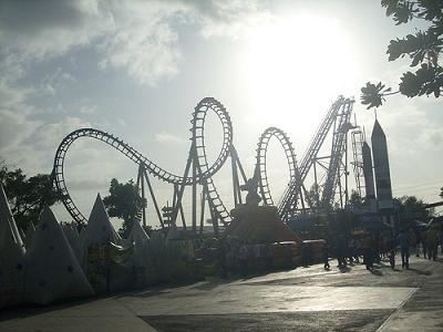
The physics of roller coasters
If you have visited an amusement park in the past, you have probably been on a roller coaster before. You know that they allow you to experience death-defying drops, extremely tight turns, and dizzying corkscrews without the risk of death or injury that you would expect to be a part of an such an adrenaline-pumping activity.
However, roller coasters a more complicated than that. Much more complicated. With every roller coaster, the laws of physics are at play, both keeping you as safe as possible, and ensuring you didn't waste your money purchasing the admission tickets.
Most roller coasters rely on gravity to supply the car with the energy needed to complete the circuit. The car is winched up to the top of the first hill, supplying it with gravitational potential energy as it starts to come down the first drop. Some roller coasters use magnetic catapults to supply the car with kinetic energy. Magnets allow the roller coaster car to accelerate extremely fast and reach mind boggling speeds in a very short period of time.
Once the roller coaster is going around the track, you experience a lot of G-forces. You feel heavier if you are going up a hill and lighter if you are going down a hill. The rider also experiences centrifugal force when going around a tight turn, and acceleration when going down hills.
While the roller coaster is going around the track, it is not propelled by any motor. It travels all by itself, with its own momentum and gravity as its sole means of propulsion. In the end, just enough kinetic energy is supplied to your roller coaster car for it to make one complete circuit around the track.
Once you complete one circuit around the track, hydraulic brakes are usually used to stop the roller coaster car. The car experiences an acceleration in the direction opposite its motion.
Here are some related to roller coasters:
How to add vectors
This blog entry will explain how to add vectors. If you follow these simple steps, you'll be adding vectors like Albert Einstein in no time:
- First step is setting your positive and negative axes. This step is crucial because it will allow you to determine whether your vectors are going in a positive or negative direction.
- Next, you must break down all of the vectors into their individual x and y vector components. For this you use the sine and cosine ratios to find the magnitudes of two x and y vector components. Next, you find the directions of the x and y components based on the positive axes you set earlier.
- You then organize these vector components in a chart while at the same time applying all of the vector transformations to the vector components. For example the vector 2A would involve multiplying Ax component by 2 and the Ay component by 2. The vector -A would involve reversing vector A and making it go in the opposite direction. Therefore, you multiply Ax by -1 and Ay by -1.
- You find the net values of all of the x and y vector components. Essentially add up all of the x values and all of the y values.
- You then use the Pythagorean theorem to calculate the magnitude of the resultant vector.
- Finally, you use the tangent angle ratio to calculate the angle of the resultant vector while paying close attention to - and +, and N, S, E, W.
- Congratulations!! You have just learned how to add vectors.
Wednesday, October 20, 2010


Tuesday, October 12, 2010
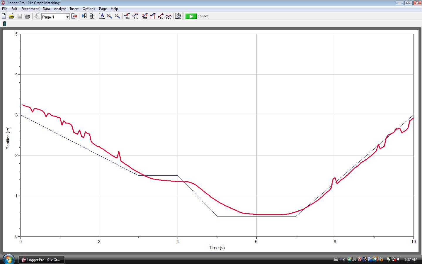
Results of the Walking the Graphs Lab
Last week, our class did a lab which involved trying to match various distance-time and velocity-time graphs by walking back and forth in front of a Vernier motion detector. Here are my group's results:
 |
| The result for experiment b. |
 |
| The result for experiment c. |
 |
| The result for experiment d. |
 |
| The result for experiment e. |
 |
| The result for experiment f. |
 |
| The result for experiment g. |
Thursday, September 30, 2010
Building an Electric Motor
Today in physics class we built a simple electric motor with groups of two. To build the motor, we used:
Here is a video of our motor spinning:
Here are some pictures of our motor:
- a piece of wood
- four 4-inch nails
- two strips of aluminum from a pop can
- 2 smaller nails
- a couple pieces of Lego
- two thumbtacks
- a kebab skewer
- a long piece of wire
- a cork
- two magnets
- some tape
The motor took me and my partner most of the period to construct. There were some minor hitches when we were unable to push the kebab skewer through the cork, but we fixed the problem by first hammering a nail through the cork to make it easier to insert the skewer.
Our motor worked based on the motor principle, which is based on the fact that when two magnetic fields interact with each other, a force is produced. In this case, the magnets produce one magnetic field, and the current running through the wires coiled around the cork produces the other magnetic field. In order for the motor to spin continuously, the current must be reversed after every half-turn. This will allow the cork to spin in one direction continuously. Our motor's spin was a bit wobbly and unstable, but it still managed to make quite a few revolutions before the power was turned off. This activity was very fun and allowed us to not only learn about the motor principle, but to apply it in a real life situation.
If we did this activity again, I would fix the motor so that spins more smoothly. I think the reason why our motor was so twitchy was because our aluminum strips were too thick, thereby slowing our motor down. If I did this activity again in the future, I would make the aluminum strips thinner.
If we did this activity again, I would fix the motor so that spins more smoothly. I think the reason why our motor was so twitchy was because our aluminum strips were too thick, thereby slowing our motor down. If I did this activity again in the future, I would make the aluminum strips thinner.
Here is a video of our motor spinning:
Here are some pictures of our motor:
 |
| Our motor during the early stages of its construction. |
 |
| Just need to add the aluminum strips... |
 |
| The finished product. |
Wednesday, September 22, 2010
Right-Hand Rules
Here are some pictures explaining the two right hand rules that I've learned so far:
 |
| The first right-hand rule (RHR#1) for conventional current flow. |
 |
| The second right-hand rule (RHR#2) for conventional current flow. |
Monday, September 20, 2010
Magnetism and Electromagnetism Notes (Text p. 582-589)
- The magnetic force is a force that acts at a distance. A magnetic field is the distribution of a magnetic force in the region of a magnet.
- There are 2 different magnetic characteristics, north and south, responsible for magnetic forces. Similar poles repel one another, dissimilar poles attract one another.
- To map a magnetic field, we use a test compass or spread iron filings near a magnet.
- Ferromagnetic metals are metals such as iron, nickel, cobalt, or mixtures of these three that attract magnets. All magnets are made up of these metals.
- Domain Theory of Magnets - All large magnets are made up of many smaller and rotatable magnets, called dipoles, which can interact with other dipoles close by. If dipoles line up, then a small magnetic domain is produced.
- Oersted's Principle - Charge moving through a conductor produces a circular magnetic field around the conductor.
- Right-hand rules used to map the magnetic field and predict the direction of the electromagnetic force created by the current running through conductor.
- Right-hand rule #1 (RHR#1) for conventional current flow (for conductors) - Grasp the conductor with the thumb of the right hand pointing in the direction of the conventional, or positive (+), current flow. The curved fingers point in the direction of the magnetic field around the conductor.
- In order to make the conductor magnet stronger and straighten our its field, the conductor is coiled into a solenoid. The magnetic field around a solenoid is like that of a bar magnet. When wire is coiled, individual field lines fall on top of each other, strengthening the overall field. Linear cylinder shape also straightens out the field.
- Right-hand rule #2 (RHR#2) for conventional current flow (for coils) - Grasp the coiled conductor with the right hand such that curved fingers point in the direction of conventional, or positive (+), current flow. The thumb points in the direction of the magnetic field within the coil. Outside the coil, the thumb represents the north (N) end of the electromagnet produced by the coil.
- Electromagnet - a coil of wire around a soft iron core, which uses electric current to produce a magnetic field.
- Strength of magnetic field represented by B.
- Factors that determine strength of electromagnet: current in the coil, number of turns in coil, type of material in the coil's centre, size of coil.
- Some of the uses of electromagnetism: lifting, relay, electric bell.
Tuesday, September 14, 2010
Resistance Notes (Text pg. 553-563)
- The amount of current flow in a circuit depends on two things: the potential difference of the power supply, and the nature of the pathway through the loads that are using the electric potential energy.
- Electrical resistance is the measure of the opposition to current flow.
- The voltage/current (V/I) ratio is constant, and therefore must be the resistance of a load because it remained unchanged through the course of the experiment.
- As a result the equation for resistance is: R=V/I, where R is resistance in Ω (ohm), V is the potential difference in volts (V), and I is the resulting current in amperes (A).
- Ohm's Law states that the V/I ratio was constant for a particular resistor.
- Many factors that affect resistance: length, cross-sectional area, type of material, temperature. (pg. 557)
- Kirchhoff's current law: The total amount of current into a junction point of a circuit equals the total current that flows out of that same junction.
- Kirchhoff's voltage law: The total of all electrical potential decreases in any complete circuit loop is equal to any potential increases in that circuit loop.
- Resistances in Series - the general equation for more than 3 resistors: R[total] = R[1] + R[2] + R[3]... + R[N], where N is the total number of series resistors in the circuit. If the resistors are all the same: R[T] = NR
- Resistances in Parallel - the general equation for more than 3 resistors: 1/R[T] = 1/R[1] + 1/R[2] + 1/R[3]... + 1/R[N], where N is the total number of parallel resistors in the circuit. If the resistors are the same: R[T] = R/N
Monday, September 13, 2010
Electricity Prelab Chart
Name, Symbol, Unit, Definition
Voltage, V, v (volt), The electric potential energy for each coulomb of charge in a circuit.
Current, I, A (ampere), The rate at which charge moves past a point in a conductor.
Resistance, R, Ω (ohm), A measure of the opposition to current flow.
Power, P, W (watt), The rate at which electrical energy is passed on to various circuit loads.
Saturday, September 11, 2010
Energy Ball Activity Questions
1) Can you make the ball work? What do you think makes the ball flash and hum?
Yes, I can make the ball work by touching both metal contacts. The ball flashes and hums because my body completes the circuit.
2) Why do you have to touch both metal contacts to make the ball work?
You must touch both metal contacts in order to complete the circuit.
3) Will the ball light up if you connect the contacts with any material?
It will light up if you connect the contacts to anything that is conductive, e.g. anything metal. However it will not work if you connect it to an insulator, e.g. rubber.
4) Which materials will make the energy ball work? Test your hypothesis.
Anything that is a conductor will make the ball work, for example anything metal.
5) This ball doesn't work on certain individuals. What could cause this to happen?
I think it could be because of a deficiency in electrolytes, or severe dehydration, or even dry hands acting as insulators.
6) Can you make the energy ball work with all 5-6 individuals in your group? Will it work with the entire class?
Yes the energy ball works with everyone in the group and with the entire class. It's just that now the conductor is a bit longer.
7) What kind of circuit can you form with one energy ball?
A simple circuit with a battery, load, and a conductor going between the two.
8) Given 2 balls: Can you create a circuit where both balls light up? 1 of 3.
Yes you can create a series circuit with two balls.
9) What do you think will happen if one person lets go of the other person's hand? Why? 2 of 3.
Both of the balls will stop working because the circuit has been broken.
10) Does it matter who lets go? Try it.
No it doesn't matter who lets go because the circuit still gets broken regardless of who lets go.
11) Can you create a circuit where only one ball lights (both must be included in the circuit)? 1 of 2.
Yes, we can create a parallel circuit where the balls run parallel to each other. This type of circuit allows one ball to be switched off while the other is still working.
12) What is the minimum number of people required to complete this? 2 of 2.
It only takes one person to make a compound circuit with two balls, but the person would have to hold the balls in weird way with both of their hands.
Friday, September 10, 2010
Series Circuits vs Parallel Circuits
Here's the difference between series circuits and parallel circuits:

Series Circuits
As you can see in the diagram above, a series circuit is a circuit in which the loads are connected one after another in a single path. As a result, there is only one path for the current to flow when traveling through the circuit.
Parallel Circuits
However, in parallel circuits the loads are connected parallel to each other, side by side. As a result, there are multiple paths that the current may take. As you can see in the diagram, when the current reaches the junction between the two light bulbs, it splits because there are two paths that the current may take. Half of the current flows through one light bulb, the other half flows through the other light bulb.
Thursday, September 9, 2010
Newspaper Structure Challenge
The physics of tall structures
- There are many forces acting upon tall structures: gravity, wind, etc.
- Many factors influence the stability of tall structures....
- The materials. The tall structure will be more stable if the materials it is made out of are strong.
- The shape. The structure will tend to be more stable if the base is wider than the top of the structure. The stability can also be improved by incorporating strong shapes like triangles into the design of the structure.
- The weight distribution. The structure will be more stable if the bottom of the structure is heavier than the top. If the top is too heavy, the structure could tip over.
- The structure's center of gravity. The structure's center of gravity should be as low as possible, right above center of its base in order to achieve maximum stability.
- It is the "imaginary point in a body of matter where, for convenience in certain calculations, the total weight of the body may be thought to be concentrated." (Source: http://www.britannica.com/EBchecked/topic/242556/centre-of-gravity)
- Could also be thought of as the "balancing point" of the structure.
 |
| Our group's finished newspaper structure. |
Electric Currents (Text P. 544-552)
Notes
Pictures and Videos
Some other useful websites:
http://en.wikipedia.org/wiki/Electric_current
http://www.physicsclassroom.com/class/circuits/u9l2c.cfm
- In an electric circuit, an energy source provides electrons with energy. Electrons are transported via a conductor to where their energy is transferred. Then they are transported back to the energy source to be re-energized.
- Current is the flow of charge: the total amount of charge moving past a point in a conductor divided by the time taken.
- The formula for current is I=Q/t, where I is current in amperes (A), Q is the charge in coulombs (C), and t is time in seconds.
- 1 ampere = 1 coulomb of charge moving through a point every second.
- Current actually flows from - to +, but in conventional current (model of positive charge flow) current flows from + to -.
- Ammeter is a device that measures current.
- DC or direct current is type of current that flows in a single direction from the power supply to the load.
- Electric Potential Difference (Voltage) is the electrical potential energy for each coulomb of charge.
- Formula for voltage is: V=E/Q, where E is the energy required to increase the electric potential of a charge, Q.
- The formula for the energy transferred by charge flow is E=VIt, where E is energy in joules, V is the potential difference in volts, I is the current in amperes, and t is time in seconds.
- A voltmeter is used to measure electric potential difference (voltage).
Pictures and Videos
 |
| Some of the various symbols used in electric circuit diagrams. |
 |
| A diagram demonstrating a conventional current. |
Some other useful websites:
http://en.wikipedia.org/wiki/Electric_current
http://www.physicsclassroom.com/class/circuits/u9l2c.cfm
Subscribe to:
Posts (Atom)